There are so many complex issues in electronics design, but no one ever gives the lowly resistor very much thought. In the overwhelming majority of cases, one simply chooses a resistor with little regard to anything more than its nominal value — and in most cases this technique works just fine. The problem isn’t so simple when an accurately-known or tightly-controlled resistance value is required — these cases often pop up when picking a resistor used for current sensing applications, configuring an op-amp for a precise voltage gain, or temperature sensing. Careful thought is required here, since variations in the value of the resistance that occur because of unit-to-unit variation as well as changes in the resistance with temperature will degrade the accuracy of the overall measurement being taken. Very often, a shotgun approach is taken to this problem — just find the tightest tolerance component you can and use that! No problem with that — until you look at the price of that 0.1% tolerance resistor in the Digikey catalogue. If the price doesn’t get you, the variation in resistance with temperature probably will — a 10k resistor with a tolerance of 0.1% will maintain that tolerance in December just as easily as it will in August, however in both of those cases it is unlikely that it will be a 10k resistor.
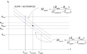
The best way to go from the standpoint of good design practice as well as cost, it makes no sense to use a resistor that is any better than what is needed to get the job done. With this in mind, I offer a simple view into how resistor tolerance and temperature coefficient are related and how they jointly determine whether or not a particular resistor is adequate for a specific application. Take a look at the graph below:

The graph is a plot of resistance over temperature. For this specific design, we require a resistor that has some “ideal” value at some “nominal” temperature. While most resistor manufacturers specify their components at 25 degrees C, it is not necessary to assume that specific temperature in this case, as our discussion is completely general. Our resistor has some component tolerance associated with it — this is shown in the graph as the narrow band around the ideal value with upper and lower values of Rtol+ and Rtol-. For any resistor that we pull out of the box and measure its resistance assuming we do so when it is sitting at its “nominal” temperature, we will measure a resistance somewhere inside the tolerance band. The wider band of resistance designated by Rmax and Rmin designate the largest and smallest values of resistance that are acceptable for the design. If we ignore any temperature effects, we easily see from the graph that as long as we choose a resistor that has a tolerance tighter than the acceptable range of resistances required by the design, the resistor will be adequate to meet the design requirements.
Bringing temperature variations into the picture makes the component selection process more interesting. The sloped lines on the graph depict the characteristics of a resistor with a negative temperature coefficient, or “tempco” — as temperature increases, the resistance decreases. Resistors can also have positive temperature coefficients — but in our analysis here it does not matter which sign the tempco is, as the results that we will present are completely general. For simplicity, we will only deal with the magnitudes of the temperature coefficients in order to avoid having to carry around a bunch of negative signs. The three sloped lines correspond to resistance over temperature for resistors that are at the positive and negative limits of the tolerance band. Notice that the temperature variation of resistance places a limit on the range of temperatures over which this particular resistor will satisfy the design requirements. For resistors with a negative tempco, the minimum operating temperature is defined by the upper tolerance limit while the maximum operating temperature is defined by the lower tolerance limit (for positive tempco, the roles that the tolerance plays is reversed).
The graph shows two equations for the slope of the lines (the slope is equal to the tempco expressed in ohms/C), corresponding to the slopes above and below the nominal operating temperature. If the nominal operating temperature is chosen to lie at the center of the overall operational temperature range, these two slopes will be equal to each other, but in general the operational temperature range need not be symmetric — in which case the slopes will be different (so as not to confuse anyone — the slopes that I am describing here are “defined” as forming the operational temperature range about some arbitrarily defined nominal temperature. The actual tempco of a resistor does not have a discontinuity at the nominal temperature).
There are two ways to approach the problem that now faces us:
- For a given operating temperature range and resistor tolerance, what is the maximum permissible tempco of the resistor?
- For a given operating temperature range and resistor tempco, what is the maximum permissible resistor tolerance?
The first approach is the easier of the two, because the answer is given simply by the expression for the slopes. The tempco of the resistor must have a magnitude that is no greater than the smaller of the two slopes given in the graphs:
![]()
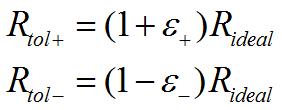
The second approach requires a bit of algebra to get the expressions for tolerance. Recalling that the upper and lower resistance tolerance limits are expressible in terms of a tolerance in the following way:

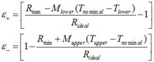
Manipulating the slope equations and using the two expressions above gives us the upper and lower tolerance values:

The maximum permissible tolerance is the smaller of the two values in the above pair of equations.
Using the results given here, it is possible to pick a resistor that will satisfy both tolerance and tempco requirements over any desirable temperature operating range. Looking at the graph, it is easy to see that tolerance and tempco interact in an expected manner —- the tighter the resistor tolerance, the larger the maximum permissible tempco for a given overall operating range. Likewise, larger tolerance resistors require smaller tempco to satisfy the design requirements over the temperature range.
As a final note, resistor manufacturers generally specify the tempco of their devices in units of parts-per-million (ppm) per degree C. In order to convert a tempco expressed in these units to units of ohms/C, use the following expression:

I hope you will find this design note useful. Feedback is always appreciated!
David
Recent Comments